Modelling mains, solar PV and BESS in a large, commercial building
Introduction
The increasing penetration of renewable energy sources in buildings is creating the concept of building-to-grid (B2G) integration. Battery energy storage systems, installed in conjunction with solar PV systems in buildings, add a layer of flexibility to the whole energy system, and are emerging as a useful resource for both the building and network operators.
Much of the literature covering the design of combined solar PV and battery energy storage systems is focused on economic assessment: by analysing building load profiles and electricity network tariffs, they look to optimise the size of the battery energy storage system (BESS) so that return on investment will be maximised. Many other sources focus on the algorithms for BESS charging and discharging to produce the greatest bill savings for the building owner.
For a building with three power sources – mains, solar PV and a BESS – the building load is not split evenly or proportionally between the sources. Load flows in the system can be complex, and made more so as a BESS acts as both a source and a load. The main goal of this report is to present an electrical power model of a building with three power sources, showing how load flow changes over a 24 hour period. It is assumed that the solar PV and BESS systems are pre sized and optimal.
Overview
Battery energy storage systems in buildings
The installed capacity of renewable energy systems, such as solar PV and wind, is increasing. Their output is inherently variable, which is presenting many challenges for network operators. Battery energy storage systems are being seen not only as a solution to mitigate some of these challenges, but also to save on energy costs for building owners.
Via the exchange of digital data between a building and the grid, on-site renewable energy systems and battery energy storage systems can support the grid or the building load, to the benefit of all stakeholders. With B2G integration, the building itself can be considered not just as a load on the grid, but as a controllable microgrid.[1]
If a building is equipped with only solar PV generation, any surplus energy generated is injected into the grid, which can cause instability where the network is not prepared for bidirectional power flows. Detrimentally for the building's operator, a low payment price may be received.
With B2G integration, a BESS can, under control, charge when network energy tariffs are low or when surplus energy is being generated by the building's solar PV, the latter reducing or eliminating injection into the grid. The BESS can, again under control, discharge to support the building load when network energy tariffs are high. The reliability of the whole energy system is increased, which is highly desirable in mission-critical installations such as data centres.[2]
A BESS can store and dispatch energy very quickly. They can be of utility scale, connected to distribution or transmission networks to aid the network operators, where they are know as in-front-of-the-meter (FTM) systems. Or, they can be installed in commercial, industrial or residential buildings, where they are known as behind-the-meter (BTM) systems.[3] This report focuses on a BTM system.
The system and model
Schematic
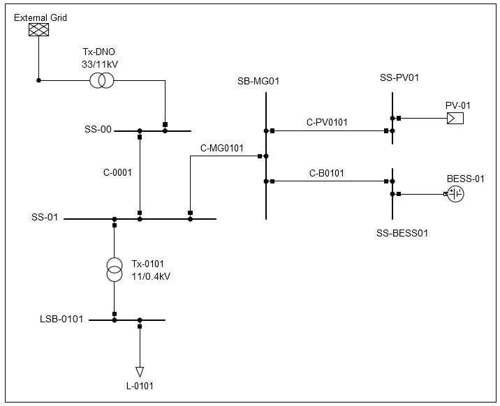
Figure 1 - System schematic, from the model.
Description
A model of the system was built using power system analysis software. A schematic, produced from the model, is shown in Figure 1. It is not a real installation (that is, it is not from a project worked on by E4B Consult) but it is a realistic installation. It is based on a research laboratory, where staff work normal office hours on weekdays. Computer servers running 'number-crunching' scientific software 24/7 are housed in a dedicated room.
A 33/11kV substation, SS-00, supplies the private, 11kV substation SS-01. The solar PV system PV-01 and BESS BESS-01 are connected at 11kV at SS-01, in parallel with the mains network. The building load is L-0101, supplied from SS-01 via the 11/0.4kV transformer Tx-0101.
Operation of the model
The model is configured to simulate a continuous 24 hour period, midnight to midnight, on a mid summer weekday. The day is cloudless, so the solar PV generates power from sunrise to sunset, peaking at midday. The network electricity tariff is considered to be relatively cheap at night, and expensive during the day. As such, the BESS is configured to charge from the mains during the night, and discharge during the day. The load flows, as calculated by the model, are shown in Figures 3 to 7.
Solar PV
The solar PV parameters are detailed in Table 1. The whole system - PV arrays, converters, coupling transformers - is contained in the component PV-01 and SS-PV01, shown on the schematic. The power output characteristics over the 24 hour period were added to the component.

Table 1 – PV-01 system data.
BESS
The BESS system parameters are detailed in Table 2. The whole system - battery racks, converters, coupling transformers - is contained in the component BESS-01 and SS-BESS01, shown on the schematic. The charging and discharging characteristics over the 24 hour period were added to the component.

Table 2 – BESS-01 system data.
Converters
Converters can be one of two main types: current source converters (CSC) and voltage source converters (VSC). VSCs can control both active and reactive power, can convert from DC to AC (termed an inverter) and from AC to DC (termed a rectifier).
Table 1 shows that PV-01 must generate active power (P) and reactive power (Q). Therefore, the solar PV component incorporates a VSC.
The BESS does not generate Q, but its converter must be bidirectional: operating as a rectifier when the batteries are charging, and as an inverter when the batteries are discharging. Therefore, the BESS component also incorporates a VSC.
The building load
The building load parameters are detailed in Table 3. The component L-0101 was configured with a load profile for a 24 hour period in mid summer, and is shown in Figure 2. The maximum load is 1.5MW, with a power factor of 0.98 lagging. It can be seen that outside of regular working hours, there is a base load of 380kW, due to the on-site computer server room.

Table 3 – Building load.
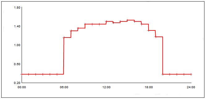
Figure 2 - Building load profile, hours v MW.
Results
Load flows from the three sources, as calculated by the model, are shown in Figures 3 to 7.
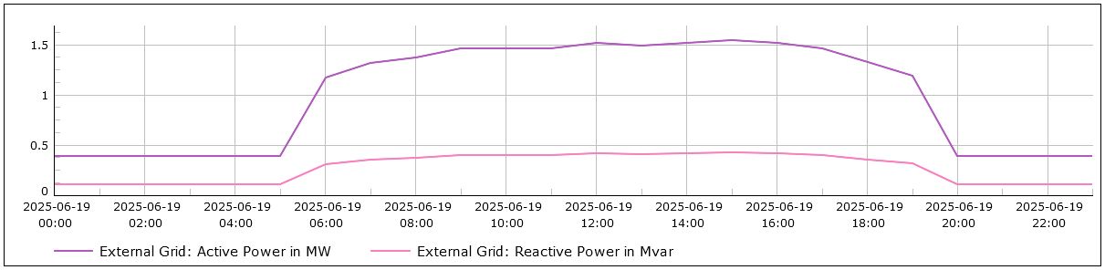
Figure 3 - Load flow from the grid, with RE out of service.
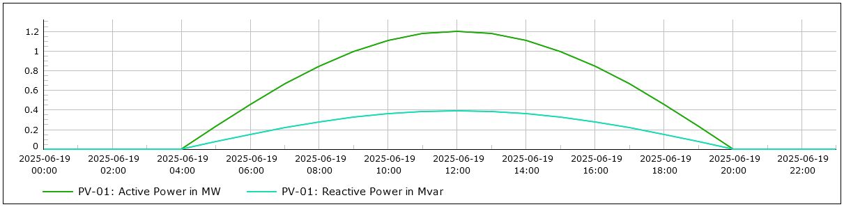
Figure 4 - Power generated by PV-01.
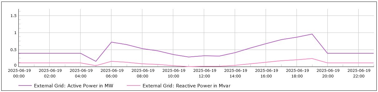
Figure 5 - Load flow from the grid, with PV-01 in service.
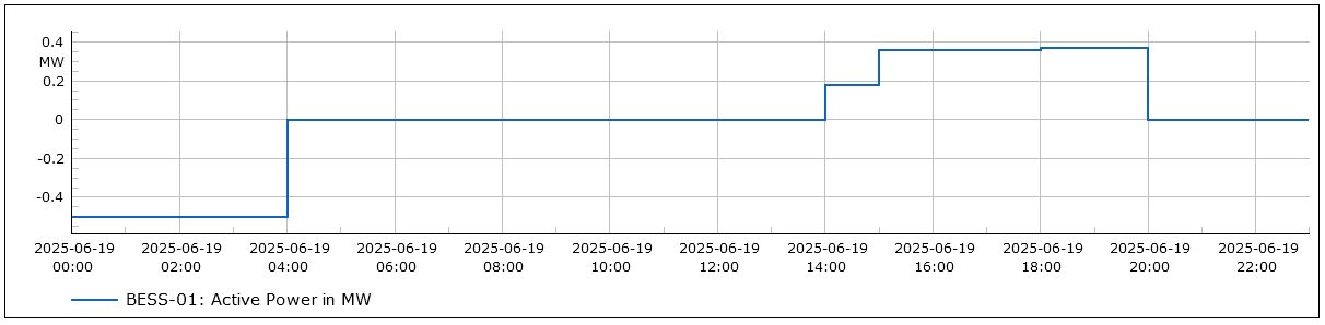
Figure 6 - Power absorbed and generated by BESS-01.
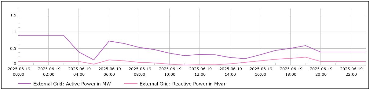
Figure 7 - Load flow from the grid, with PV-01 and BESS-01 in service.
Discussion of results
Without a microgrid
With no contribution from PV-01 or BESS-01, Figure 3 shows the power at SS-00 supplied by the grid. The profile correlates with the load profile seen in Figure 2. Most energy use is during the day, when tariffs are high.
With solar PV
Figure 4 shows that the solar PV system is generating both active and reactive power between approximately 04:00 and 20:00, peaking at 1.2MW at midday. Figure 5 shows the subsequent demand on the grid, which is a reduction from that shown in Figure 3.
With solar PV and BESS
The power profile of BESS-01 is shown in Figure 6. When the power on the graph is shown as negative, the system is charging: absorbing power from the network. When positive, it is discharging: supplying power to the installation. It can be seen that the BESS is set to charge between midnight and 04:00 hours, taking advantage of low energy tariffs during the night. It supplies energy into the installation between 14:00 – 19:00 hours, supporting the solar PV system in reducing the demand on the network supply while tariffs are high. The resulting reduction in demand on the grid can be seen by comparing Figures 7 and 3.
An electrical engineering perspective
The graphs in Figures 3 to 7 show that an electrical installation with three independent power sources can be modelled over a period of time, and used to evaluate the operation of the system as a whole. The results can be used to inform detailed electrical design such as CPD selection and settings, and cable sizing.
Conclusions
In a large commercial building with both mains and on-site renewable energy sources, load flows in the system can be complex. With B2G integration, the exchange of digital data between a building and the grid can be used to control the operation to the benefit of all stakeholders. By creating a model of the system using power system analysis software, the system can be analysed from an electrical engineering perspective.
References
[1] Schneider Electric. Building-to-Grid Integration for More Efficient, Sustainable, and Resilient Energy Systems. White Paper 517. 2022.
[2] Correia, A.F.M.; Moura, P.; de Almeida, A.T. Technical and Economic Assessment of Battery Storage and Vehicle-to-Grid Systems in Building Microgrids. Energies 2022, 15, 8905.
[3] ABB. White paper - Utility-scale battery energy storage system (BESS). 2021
Contact
Enquiries are welcome from M&E contractors, consultants and renewable energy system developers.
How can we support you with your electrical design tasks?
Contact details here ...
